Sputter coaters
We have two different sputter coaters available in our lab.
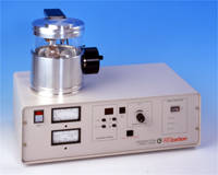
The Cressington 208C (Carbon)
The Cressington 208 is used to apply a thin carbon layer to non-conductive samples prior to SEM imaging, and is suitable for imaging at higher magnifications where metal sputter coating particles become visible. It is also the recommended coater for EDX analysis since Carbon will not absorbe and fluoresce as much as other metallic coating.
Specifications
- Microprocessor controlled automatic mode, plus manual mode
- Continuous and pulsed mode
- Manual tilt, motorized rotating stage
- Thickness monitor
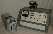
The Anatech Hummer VI (Au/Pd)
The Anatech Hummer VI is a metal sputter coater currently setup with a Gold-Palladium target. It is used to apply a metal coating to non-conductive samples for imaging in the SEM.
Specifications
- Continuous and pulse modes
- Degauss function to remove static charge from samples
- Gold-Palladium alloy target
These instructions are also available for download in pdf format.
Notes:
- Do not touch anything inside the chamber without first wearing gloves.
- Each sharpened carbon rod will typically yield three to four runs of six seconds each. If you start the coating run and it stops before the predermined time, the rod must be replaced.
Operating instructions:
- Put on gloves.
- Lift open top of chamber.
- Remove glass cylinder, and clean it with Kimwipes and aecetone, followed by Kimwipes and ethanol to remove carbon film, and place it on its side on clean aluminum foil.
- Install carbon feed rods. Be sure to sand smooth the ride side rod, and install a rod with sharpened tip on the left side.
- Install samples on stage and ensure they stay in place when stage is spinning.
- Tilt stage if you need to coat the sides of your specimen.
- Reinstall glass cylinder.
- Close top of chamber.
- Turn on stage rotation (use speed 4 out of 5).
- Press power switch to ON.
- When vacuum reaches better than 10-4 mbar (takes about 4 minutes), ensure auto/manual switch is set to auto, and press Start. Instrument will run for six seconds, which yields approximately 1.5 nm thick film.
- Wait at least two minutes for the carbon rods to cool, and vacuum to reach better than 10-4 mbar, and repeat step 11 until required thickness obtained.
- When finished coating, press Power to turn off the instrument. WAIT FOR TURBO PUMP TO GO COMPLETELY SILENT BEFORE OPENING CHAMBER OR YOU WILL DAMAGE THE PUMP.
- Remove glass as before and remove samples.
- Clean glass as before and reinstall on instrument, and close the lid.
- Sign log book.
These instructions are also available for download in pdf format.
Notes:
- Do not over tighten the nitrogen supply needle valve, or it will be damaged. When closing this valve, once you feel resistance, STOP IMMEDIATELY.
- Do not touch anything inside the chamber without first wearing gloves.
Operating instructions:
- Ensure power switches are off.
- Put on gloves.
- Lift open chamber lid, do not shake or move top suddenly to prevent target from detaching.
- Lift off glass cylinder, place on it's side on the stand provided on top of the sputter coater.
- Place sample stub(s) inside chamber. Sample stub should be 1.5 inches from the target. If sample height needs adjusting, please consult staff.
- Replace glass cylinder, and lower chamber lid into place.
- Gently apply pressure to the chamber lid, and turn on the power switch. Once the vacuum pump starts and vacuum gauge shows vacuum, you can release pressure on the chamber lid.
- Adjust needle valve to closed position (DO NOT OVERTIGHTEN), and allow chamber to pump down to approximately 30 mTorr.
- Turn on the Argon gas valve at the top of the tank.
- Open needle valve wide to flush chamber with Argon, allow vacuum gauge to read 500 mTorr or higher. Close needle valve, and wait for chamber to pump down to approximately 30 mTorr.
- Repeat flushing of chamber once more.
- Adjust needle valve so there is between 55 mTorr to 70 mTorr of Argon in the chamber.
- Turn on high voltage control switch, and adjust voltage control knob until plasma discharge current reads 10 mA.
- It may be necessary to make slight adjustments to needle valve and voltage dial to maintain a plasma discharge current of 10 mA.
- Start your timer as soon as you see the plasma glow.
- Once your desired timer has expired, turn off the high voltage control switch, and open the needle valve wide open to flood the chamber back to atmospheric pressure.
- Lift the lid, extract your sample(s). Return lid to closed position.
- Turn off Argon gas supply valve at the top of the tank, unplug sputter coater.
To better understand the coating rate (we do not have a thickness monitor attached), two samples were made.
Method:
- A piece of polished Gallium Arsenide was used as a substrate.
- Layers of Carbon were deposited with the Cressington 208 between different thickness layers of Au-Pd to clearly separate the Au-Pd layers from each other and from the substrate. Hummer VI parameters were 75 mTorr Argon and 10 mA current, with 1 minute, 2 minute, and 3 minute run times.
- A Tungsten protective pad was laid down and a TEM section was lifted out of this bulk sample and attached to a half-grid in the FB-2100, and thinned sligthly to reveal the layers of Carbon and Au-Pd with the capping layer of Tungsten.
- This grid was mounted to an SEM stub and carbon coated for conduction, and then imaged in the S-4800 SEM to determine Au-Pd layer thicknesses.
The two samples were made separately, to determine level of consistency in the coating runs. Each sample A and B were imaged in three locations, and thicknesses measured.
- Sample A: Location 1, Location 2, Location 3
- Sample B: Location 1, Location 2, Location 3
The average thickness of the depositions were:
Sample A:
- 1 minute runtime: 9.76 nm
- 2 minute runtime: 14.55 nm
- 3 minute runtime: 19.18 nm
Sample B:
- 1 minute runtime: 11.58 nm
- 2 minute runtime: 15.54 nm
- 3 minute runtime: 21.17 nm
This is a completely scientific study with statistical significance, but the results seem mostly consistent. For simplicity the thicknesses can be approximated as:
- 1 minute runtime: 10 nm
- 2 minute runtime: 15 nm
- 3 minute runtime: 20 nm